Back to articles
Regular Articles
Volume: 1 | Article ID: jpi0113
Image
Light-Field Appearance Editing based on Intrinsic Decomposition
  DOI :  10.2352/J.Percept.Imaging.2018.1.1.010502  Published OnlineJanuary 2018
Abstract
Abstract

The authors present a framework for image-based surface appearance editing for light-field data. Their framework improves over the state of the art without the need for a full “inverse rendering,” so that full geometrical data, or presence of highly specular or reflective surfaces are not required. It is robust to noisy or missing data, and handles many types of camera array setup ranging from a dense light field to a wide-baseline stereo-image pair. They start by extracting intrinsic layers from the light-field image set maintaining consistency between views. It is followed by decomposing each layer separately into frequency bands, and applying a wide range of “band-sifting” operations. The above approach enables a rich variety of perceptually plausible surface finishing and materials, achieving novel effects like translucency. Their GPU-based implementation allow interactive editing of an arbitrary light-field view, which can then be consistently propagated to the rest of the views. The authors provide extensive evaluation of our framework on various datasets and against state-of-the-art solutions.

Subject Areas :
Views 69
Downloads 17
 articleview.views 69
 articleview.downloads 17
  Cite this article 

Shida Beigpour, Sumit Shekhar, Mohsen Mansouryar, Karol Myszkowski, Hans-Peter Seidel, "Light-Field Appearance Editing based on Intrinsic Decompositionin Journal of Perceptual Imaging,  2018,  pp 010502-1 - 010502-15,  https://doi.org/10.2352/J.Percept.Imaging.2018.1.1.010502

 Copy citation
  Copyright statement 
Copyright © Society for Imaging Science and Technology 2018
  Article timeline 
  • received February 2018
  • accepted June 2018
  • PublishedJanuary 2018

Preprint submitted to:
jpi
Journal of Perceptual Imaging
J. Percept. Imaging
J. Percept. Imaging
2575-8144
Society for Imaging Science and Technology
1.
Introduction
Light-field technology offers many advantages with respect to traditional 2D imaging, as it enables depth estimation, refocusing, as well as view-dependent effects such as glossy reflections and motion parallax that are desirable in many applications such as virtual reality (VR). Typically narrow-baseline light fields with dense angular views and low spatial resolutions are considered due to the accessibility of inexpensive capturing hardware such as the Lytro camera. Since such light fields exhibit strong redundancy of data between views and offer only a limited freedom in virtual camera placement and manipulation, sparse and wide-baseline light fields are increasingly gaining attention [1]. In this work, we present a framework to extract consistent intrinsic components (e.g, shading and reflectance) of sparse light-field data in order to simulate different perceptual effects that alter the appearance of the objects in the scene. Unlike most light-field-based methods [2, 3], we do not make any strong assumptions on the structure of the light-field data. We do not require high number of views or small baselines; however, our approach generalizes to such cases as well.
Surface appearance and material editing is often achieved by a full inverse rendering where a 3D geometry is estimated along with an environment map [4], and then an altered version of the scene is rendered. The quality of such results are subject to the soundness of the extracted geometry and environment map, which might require highly specular objects in the scene [4, 5] or the sky visibility [6]. Even modest amounts of inaccuracy or noise in the reconstructed 3D model and lighting can lead to visible artifacts that might easily ruin all material editing efforts. In fact, such inverse rendering approaches might not be strictly required, as recent findings on material discrimination and recognition indicate that the human visual system (HVS) does not perform physically correct inverse optics simulation [7, 8].
A general study of such heuristics is done in [9] and [10]. Specific analysis of human perception with respect to glossiness and translucency is carried out in [8] and [7], respectively. Further, in [11], the authors discuss the link between spatial frequency bands of an image and material perception. Overall it has been shown that HVS relies on built-in heuristics that connect certain image patterns with material properties. The above indicates that editing image patterns by skillful filtering of different intrinsic layers may provide better visual quality than artifact-prone full inverse rendering.
Inspired by the band-sifting concept, proposed by Boyadzhiev et al. [12], we simulate the appearance of different materials and surface structures consistently on light-field data. Instead of band sifting the luminance channel, we process intrinsic layers, which significantly increases the variety of material edits, as they can precisely be targeted on textures, geometric details, or glossiness. Due to intrinsic layer separation we can introduce new, perceptually justified band-sifting operations, which lead to meaningful appearance changes such as opaque-to-translucent object conversion. We can also make more profound editing effects, for the appearance changes that have already been demonstrated by Boyadzhiev et al., without unwanted side effects.
Contributions: We propose a framework for light-field appearance editing with the following contributions.
An intrinsic image decomposition method which, unlike existing work, is capable of handling wide-baseline light field assuring consistency between views.
Extension of the band-sift filtering using intrinsic image layers to improve its performance and robustness while maintaining consistency between views.
Demonstrate how to reproduce and manipulate complex perceptual appearance effects (e.g, translucency, pearlecency, wetness) by means of purely image-based methods.
GPU-based interactive image editing framework.
2.
Related Work
In this section, we discuss existing solutions to image, video, and light-field decomposition into intrinsic components. Then, we summarize the work on light-field manipulation, with special focus on material and appearance changes. Since such efforts are relatively sparse, we broaden our discussion to the manipulation of single images and videos with similar goals in mind.
2.1
Intrinsic Image Decomposition
The term intrinsic images is first introduced in the literature by Barrow and Tenenbaum [13] to refer to mid-level components like reflectance and shading. A comprehensive survey of Intrinsic Image Decomposition methods is presented by Bonneel et al. [14] where different methods are categorized based on their assumptions and choice of priors. Here, we focus on methods that employ additional scene information beyond a single RGB image and discuss representative examples of such methods.
Chen et al. [15] use RGB-D to implement surface normal priors. Nonetheless, a depth image does not provide enough information about the scene to perform a full inverse rendering and complexities like cast shadows remain ambiguous. Similarly stereo matching-based methods [16] use disparity to infer some level of geometric information in order to introduce additional constraints and improve the results while maintaining consistency between the two views. Image sequences containing camera or scene motion could be used to further resolve ambiguities [17]. Multi-view stereo-based methods [6, 18] use a 360 view of the scene to extract full geometry and environment map.
Light field as a special case of multi-view stereo, provides some level of angular information which could improve decomposition in the presence of view-dependent components such as specularity [3]. In addition, disparity information can be extracted which allows the inclusion of geometry prior. Similar to the case of stereo and RGB-D, geometry cues might not be helpful in resolving complexities like cast shadows. However, multiple instances of the same data might improve the decomposition robustness, e.g., in the presence of noise.
To the best of our knowledge, there are two intrinsic image decomposition methods for light fields in the literature [2, 3]. They both require highly dense light field with small baselines. On the contrary, our method is capable of handling a sparse set of views and a large baseline. In terms of optimization priors, we show that by focusing on reliable and well-crafted priors, we are able to outperform existing methods which often use more complex priors [14]. Our method is capable of handling both dense and sparse light field.
Artusi et al. [19] provide an extensive survey on specularity removal in natural images. While a vast majority of intrinsic image decomposition methods ignore specularities [2, 16, 17, 20], some successful attempts have also been reported [3, 21, 22]. However, these methods focus on narrow-baseline, dense light fields, and are not directly applicable to sparse light fields. Also, while aiming at physically correct specularity extraction, many failure cases are reported for such methods [23] that might lead to visually disturbing artifacts, e.g, for large area highlights. In our application the extraction of specularity layer can lead to many interesting appearance editing effects. We resort to more approximate solutions that do not lead to obvious visual artifacts in our appearance editing at the expense of physical correctness. A detailed review of gloss perception is done in a recent study by Chadwick et al. [24]. We take inspiration from [8] and [10] to extract a psuedo specular/highlight layer from a given image.
2.2
Image/Light-field Editing and Enhancement
Multi-scale edge-preserving image decompositions have been used to enhance image detail or to achieve other image appearance changes or transfers [2529]. We also perform a multi-scale image decomposition, but we apply it to intrinsic image layers, which gives us a better control over the wide range of effects we can produce. Recently, deep/machine learning methods have been successfully used for overall image appearance changes and various stylizations [30], but spatially selective, continuous range, and large scope material editing that is intuitive to the user has not been demonstrated so far.
Light-field manipulations [31] focused mostly on retargeting [32], shape deformation [33], in-painting and recolorization [34], compositing [35], and morphing [36]. However, research on light-field appearance editing is relatively sparse [37, 38], and the key problem that is considered there is intuitive propagation of sparse user edits to all views [39, 40].
2.3
Image/Light-field Material Editing
Material appearance editing based on a single image has widely been investigated [4, 5, 4145]. In all these cases, an attempt of inverse rendering has been performed. Since the problem of reconstructing all needed data from a single image is strongly under-constrained [46], manual intervention might be required to reconstruct the missing scene lighting or geometry information [5, 44].
Gryaditskaya et al. [23] recover such information from light fields, which is then employed in a spatio-angular filter that enhances the roughness of glossy objects. To our knowledge, this is the only work where material appearance editing has been investigated for light fields, and while the full inverse rendering has not been performed, the filtering quality relies on the accuracy of normal vector reconstruction. The scope of roughness manipulation is limited and even simple roughness reduction has not been shown in this framework.
Many successful editing examples have been presented in the discussed work, which was greatly facilitated by the limited sensitivity of visual system for even substantial departures from physical correctness [5, 7, 8, 47]. However, the 3D scene data, as required by these techniques, is often reconstructed with low precision, which might lead to visible artifacts, or at best reduce the generality of proposed manipulations. In this work, we rely on a much simpler, purely 2D approach, and we take an inspiration from the work of Boyadzhiev et al. [12] who introduce the band-sifting operations.
The relationship between image statistics and reflectance perception is discussed in [9, 10]. In [8], the perception of glossiness is explored using visual cues. Band sifting is a simple and effective technique for image-based material editing based on above findings. The basic idea is to do a multi-scale decomposition of luminance channel into a set of subbands. And then selectively manipulate these subbands based on frequency, amplitude, and sign. The manipulation is pretty simple where the selected part of subband is either boosted (multiplied by a factor greater than 1) or reduced (multiplied by a factor between 0 and 1). The above relationship between 2D frequency bands and material perception is discussed in [11].
We are different from [12] in the way that we introduce a new invert operation in addition to the previous reduce and boost operations. By applying operations individually on intrinsic layers, we are able to achieve new kinds of material editing effects. Moreover, the range of these manipulations is also increased.
Intrinsic images/videos have been used for material editing [17, 48], but only recoloring and tone mapping curve manipulations have been demonstrated, respectively, for the reflectance and shading layers. In this work, we additionally consider the specular layer, and a wider scope of material manipulations.
3.
Overview
In this section, we provide an overview of our framework for appearance editing as shown in Figure 1. The input light field is first white balanced and then decomposed into mid-level intrinsic layers (Section 4). These layers allow us to control different aspects of the surface appearance such as texture (reflectance), fine geometrical details (shading), and glossiness (specularity). By applying band-sifting operations to each layer separately and combining them together, we achieve novel appearance and material looks (Section 5).
Figure 1.
Flowchart of the complete system for image-based material appearance editing in light fields.
4.
Light-field Intrinsic Layer Decomposition
We base our intrinsic image extraction on Grosse et al. [49] providing a simplified dichromatic reflection model Eq. (1), where an input image I is described as the sum of diffuse Id and specular C components, and the diffuse component itself consists of shading S and reflectance R.
(1)
Ix=Ixd+Cx=SxRx+Cx.
Here the multiplication and addition operations are pixel wise. For brevity, we omit pixel coordinates x unless required. It is common in the literature to use logarithmic scale in order to further simplify the Id term into id = s + r. In the above formulation lower case letters id, s, and r denote the respective log values of Id, S, and R. As we are dealing with light fields, we enforce consistency between views by jointly optimizing over all pixels in all views.
4.1
Pre-processing
Real-world scenes are often illuminated by non-white light sources and contain glossy surfaces with specular highlights, which is typically ignored by existing intrinsic decomposition methods [2, 16, 17, 20]. In this work, we introduce a pre-processing step to correct illumination color and extract specularity. This allows us to simplify intrinsic image decomposition to the generic problem, where it is assumed that Lambertian surfaces are lit by achromatic light. In Figure 2, we show our decomposition results with and without this pre-processing step for a better and fairer comparison to the above mentioned methods.
Figure 2.
Comparison of the reflectance layer extraction using our (with/without the pre-processing step consisting of specularity removal and white balancing), Graces et al. [48], Meka et al. [17], and Bell et al. [20] methods. Light fields for two natural scenes composed of 101 views (1 cm baseline between neighboring views) have been used and only the first and last views are shown. As Garces et al. and Meka et al. rely on dense data, all 101 views are used. But for our method, we subsample only 11 equally spaced views (10 cm baseline). For Bell et al. we perform decomposition separately on each view. While no method is perfect, our reflectance results contain much less shading, specularity, and no patch-like artifacts. Our results are consistent not only between view, but also within each view (e.g. the red chair). Please refer to the supplementary material for the shading results. Original images are taken from [67].
We estimate the illumination chroma using the general gray-world approach [50], which is based on the assumption that “the pth-Minkowski norm of a scene is achromatic after local smoothing.” We based our illumination estimation on Eq. (17) in [50], and we found that p = 3 performed well for our goals. To white balance each image, we divide each pixel color by the estimation of normalized illumination color (preserving its brightness).
As our approximate specular layer extraction is based on band-sifting operations, we provide all relevant details in Section 5.1 after band sifting is properly introduced.
4.2
Reflectance and Shading Layer Extraction
Current light-field decomposition methods use epipolar images to derive the intrinsic layers [2, 3]. This requires narrow-baseline and dense light field with a known structure. Our method, on the other hand, is designed for sparse light fields and wide baselines where such techniques are not applicable. Therefore, we regard light field as a generalization of stereoscopic images, and we refer to methods that consider stereo pairs [16, 51].
Bonneel et al. [14] states that many complex intrinsic image methods are not better than the baseline for image editing, and some priors may be even harmful. Please note that the baseline correspond to simply assigning chroma to reflectance and brightness to shading. Having an overcomplex optimization with several weak (ill-posed) energy terms does not always provide a benefit. Instead, our intrinsic image optimization is tailored particularly to appearance editing needs.
Since white-balancing operation is performed in the pre-processing step (Section 4.1), we assume grayscale shading. The main goal in intrinsic image decomposition is decomposing pixel intensity into reflectance and shading. Many works in the literature [2, 16, 52] choose to solve for shading, and then compute reflectance using, r = ids. We found that often existing light-field datasets contain some inconsistencies regarding image brightness due to e.g., flickering light. By definition, reflectance is invariant to illumination. Therefore, we formulate our optimization by solving for reflectance instead of shading. This further simplifies formulation of our optimization:
(2)
argminrE(r)=λrEr(r)+λdEd(r)+λaEa(r)+λsr1
where Er, Ed, and Ea are retinex, disparity, and absolute shading scale terms, respectively with their corresponding weights, and λs is a regularization parameter assuring reflectance sparsity.
We use fixed weights λr = 2, λd = 1, λa = 0.7, and λs = 0.1 for all the results presented in this article. In the supplementary materials, we provide an analysis of these parameter weights along with additional results. Below, we provide an explanation of each term.
4.2.1
Retinex Term:
One of the most fundamental concepts in intrinsic image decomposition is Retinex. It can be inferred from the evaluation results in [14] that the methods which use a strong Retinex constraint achieve results better suited for image editing. Based on Retinex theory, large derivatives in the image are attributed to reflectance and small derivatives to shading. We formulate this as follows:
(3)
Er(r)=mnNm[ζmn(rmrn)2+(smsn)2]=mnNm [(1+ζmn)(Δrmn)2+(Δimn)22ΔimnΔrmn ]
where m is any pixel in the light-field data, Nm are its immediate bottom and right neighbors. We used sm = imrm, Δrmn = rmrn, and Δimn = imin.
The weight ζmn allows the optimization of reflectance to differentiate between shading and reflectance edges, smoothing out the former and preserving the latter. A crucial step for a good Retinex term is to correctly classify variations in the image (i.e, edges) to shading and reflectance. Existing methods often rely only on chroma [2, 16] to find reflectance edges. This results in disregarding non-chromatic reflectance edges that are often very important (refer to numbers, eyes, and text in Figure 3). While [2] tries to solve this issue by separately detecting the black and white pixels, both methods over-smooth the grayscale reflectance edges and are not able to preserve them (Fig. 3). Bell et al. [20] use a weighted variation of RGB.
Figure 3.
Comparison of the reflectance layer extraction using our, Garces et al., Xie et al. and Chen et al. methods. Each method has a different input: Ours uses 11 subsampled view (10 mm baseline) and given disparity, Garces et al. uses 50 dense view (2 mm baseline), Xie et al. [16] uses these two view and given optical flow, and Chen et al. is performed separately for each view given the existing disparity. Note that contrast is lost (the eyes and text) for Garces et al. and Xie et al., there are inconsistency problems for Garces et al., and more shading component remains for Chen et al.
We use color gradient, ∇Cg, introduced by van de Weijer et al. [53] to better identify true reflectance edges. This gives us sharper reflectance edges and avoids flattening and averaging of strong brightness edges in the reflectance. Many Retinex-based methods [2, 16] choose a binary weight for reflectance by applying a threshold. As we already remove the noisy values, we choose a soft threshold scheme to normalize ψmnr in the range of [0,1]. Even though color gradients perform reasonably well, we believe that a perception based reflectance edge would give better results. Modifying the edge weights based on human perception and analyzing its impact would be an interesting idea for future work. Thus, the final weight ζmn is calculated as follows:
(4)
ψmnr=0Cg(rm,rn)<5Cg(rm,rn)otherwise
(5)
ζmn=(1.0+e(γ(ψmnrα)))1
where we found α = 5 and γ = 0.5 to perform best in variety of scenes and datasets. The significance of the retinex term is to compute the reflectance of different views of the light field. We do not enforce any similarity constraint between reflectance of different views in this term. However, due to joint optimization we get some implicit consistency between views.
4.2.2
Disparity Term:
This term enforces neighboring views to have a consistent reflectance. Therefore, we first need to compute correspondences for such view pairs. In [16] they use dense optical flow. However, we use disparity computed from depth wherever it is available, and otherwise use Deqing Sun’s implementation of Black and Anandan’s dense optical flow method [54, 55]. The disparity term is formulated as:
(6)
Ed(r)=mωmmocc(rm(j)rm(j+1))2
where j is the index of a view in light field i.e., every two consecutive views contribute to the disparity term. m and m denote two corresponding pixels. We only constrain those pixels which are not occluded. In case optical flow is used for matching, occlusion map is simply computed using a forward/backward check of the flow field with zero thresholding to enforce consistency. However, in case depth is available, similar to [2] we compute occlusion mask using normalized depth D:
(7)
ωmmocc=0.01|DmDm|>0.011otherwise.
Please note that one might be tempted to use such occlusion masks, to enforce consistency, in the retinex term as well. However, by doing so we lose information due to missing data in each view. Note that, light-field data is mostly redundant unless there is a large baseline and parallax; therefore, disparity term is most effective in these cases. When reducing computation time is a priority and depth information is not available, user might choose to disable disparity for a dense diffuse light field. However, we observed that disparity term improves the quality of the results especially in case of noisy images and flickering illumination. As mentioned in Section 2.1, while some methods use surface normals information extracted from disparity, we found using a prior on surface normals to be less effective as these estimated normals are noisy and often not effective enough to disambiguate complexities like cast shadows.
4.2.3
Absolute Scale Term:
It is widely known in the intrinsic image literature that the absolute scale of intrinsic shading and reflectance layer is ambiguous; and therefore, each method estimates these values up to a constant magnitude. In our particular appearance editing application, extreme shading values (especially black and white shading edges) could result in artifacts when e.g., boosting wrinkles or producing a translucent effect. We solve this by adding a constraint on shading magnitude which prefers moderate values. Such constraint has been used by Xie et al. [16] considering only the brightest pixel, or Bell et al. [20] constraining every pixel. Constraining the brightest pixel often is not enough, and due to dimensionality of the light-field data considering each pixel is too expensive. Instead, we find constraining 25% of all pixel uniformly sampled from each view to be a good trade-off. Therefore, we formulate this term to penalize extreme shading values on sampled pixels and squeeze them toward a constant s̄=log(0.5).
(8)
Ea(r)=j|sjs̄|2=j|ijrjs̄|2.
4.2.4
L1 Regularization:
We use the method of [56] to further penalize L1 norm of reflectance. This enforces sparsity in the reflectance image which can replace local and non-local constraints on reflectance introduced in [16]. Final optimization problem can be simplified as the following regularized least squares problem:
(9)
minrTrd22+λr1
T represents the constraint matrix, d is a vector representing the R.H.S of all our constraint equations and r is the unknown reflectance. In all our experiments λ = 0.1 gives reasonable results. Garces et al. [2] use a L1 filtering as a pre- and post-processing step to improve consistency and reduce noise. Instead we use L1 regularization as an integral part of our optimization improving the quality of our estimation results.
Many existing methods use a reflectance clustering scheme to further achieve global reflectance sparsity [17, 20, 48, 57]. However, such clustering can be quite sensitive to the choice of number of clusters as well as the effectiveness of the chosen color space and correctness of white balancing. In general, clustering tends to be more suitable for scenes which contain a limited sparse set of colors. More complex and natural scenes, especially from nature and landscape, often do not follow the global reflectance sparsity assumption. Therefore, in the current work, we take advantage of our edge-based local sparsity scheme.
4.3
Extension to Dense Light fields
In case of a dense light field, the first step is to do a sparse sampling. The intrinsic decomposition of the sparse samples is performed using the method described in Section 4.2. The sparse reflectance is then propagated among all the views to get a dense reflectance output. Let us consider that we have sparse reflectance for views at position a and c, given by Ra and Rc respectively.
The reflectance at intermediate position b, say Rb, is obtained by finding a minimizer for the energy functional in Eq. (10).
(10)
E(Rb)=Ω(1ζmn)(RbIb2)+wa(RbTab(Ra)2)+wc(RbTcb(Rc)2).
Please note that ζmn was used to avoid smoothing of reflectance at reflectance edges (refer Eqs (3) and (5)). In Eq. (10) we use 1 − ζmn to impose gradient domain constraint only at reflectance edges. In Section 4.2 we discuss how these edges are obtained. The weights wa and wb represent the quality of image mapping. Tab is a warp operator that maps view Ia to Ib and Tcb is a warp operator that maps view Ic to Ib. We use the same warp operators to map reflectance Ra and Rc. The energy formulation is based on the idea introduced in [58] and further explored in [59].
However, we have modified this energy for our specific purpose. The first modification is introduced in the form of a weight, 1 − ζmn for the first energy term. By introducing such a weight, reflectance is enhanced while it is being propagated to dense views. The second modification is making use of two neighboring views, in the angular domain, and their sparse reflectance in the energy formulation. In [59], the authors consider only one previous view in temporal or angular domain. By making use of two nearest neighbors we ensure better consistency among views and also faster convergence for energy minimization. A detailed discussion of the sparse reflectance propagation is presented in the supplementary material.
5.
Light-field Appearance Editing
In this section, we extend band sifting of the luminance channel as proposed in [12] to independent processing of each intrinsic image layer as derived in Section 4. In Section 5.1 we revisit the problem of specularity removal. We describe how an approximate pseudo-specular layer extraction can be done using band sifting. In Section 5.2, we provide a brief description of some of the effects achieved using our sifting-based material and appearance editing framework. We show examples of applying these effects to real-world scenes. In Section 5.3 we compare our editing framework with [12] in terms of quality and robustness for effects like weathering and metallic look. In Sections 5.2 and 5.3 we use ground-truth intrinsic layers for a fair evaluation of our appearance editing module and demonstrating its strength (see Figures 4 and 5). All the remaining results in the article make use of our full framework (including intrinsic layers). We further introduce new effects such as pearl and translucency in Section 5.4.
Figure 4.
Different type of material edits using our framework, (b) sift operation: S(HLA, 10) (c) sift operation: R(LLA, 10) (d) sift operation: C(AAA, 3) (e) sift operation: S(HHA, −5), R(HAP, −6), and C(LAA, 4) (f) sift operation: R(HHN, 5.5) and C(HHN, 5.5). The top left of each image shows a zoomed in version of the region marked by the blue rectangle in (a). Original image and ground-truth intrinsic layers are taken from [61].
Figure 5.
Comparison of our sifting framework with original luminance-based band sifting, (a) sift operation: S(HHP, 3) and C(HHP, 8) (b) sift operation: L(HHP, 8) (c) sift operation: S(HLA, 9), R(AAA, 0.6), and C(AAA. 08) (d) sift operation: L(HLA, 9). The top left of each image shows a zoomed in version of the region marked by the blue rectangle in (a).
Based on Eq. (1) we introduce the following notation to describe band sifting of image I (also refer to Fig. 1):
(11)
I=S(fsasss,κs)R(frarsr,κr)+C(fcacsc,κc),
where flalsl represents a component of intrinsic layer ls, r, c that undergoes band sifting. Each component of flalsl is characterized by the following signal categories: spatial frequency fl, signal amplitude al and its sign sl. Similar to [12], we allow only a predefined set of subcategories: fl ∈{H, L, A}, al ∈{H, L, A}, sl ∈{P, N, A}, where H and L denote high- and low-frequency/amplitude range, P and N represent positive and negative values, and A stands for “all,” i.e, the complete category. By controlling the value of multiplication factor κl, we can boost (κl > 1) or reduce (0 < κl < 1) the selected component of the image signal. In addition, we extend over  [12] by supporting negative values of κl introducing a new invert operation. For some of our material edits we modify the saturation of reflectance layer. The modification is governed by a multiplication factor κd, where κd > 1 depicts an increase and 0 < κd < 1 implies a decrease in saturation respectively.
Note that in this notation only a single component of each intrinsic layer might undergo band sifting, and the remaining signal in such layer remains intact. In practice, such a manipulation scope is sufficient to achieve most appearance changes presented in this work. In Section 7, we discuss ideas for manipulating multiple components per each intrinsic layer.
An example operation where we boost the high (H) frequency, low (L) amplitude, and positive (P) components of shading layer by a factor of 4 can be written as: I = S(HLA, 4) ⋅ R + C. Note that in the above example reflectance and specularity layers remain unchanged. We use L(fLaLsL, κL) notation to indicate when we mean the original band sifting [12] where an operation is performed on the luminance channel L of the image instead of on its intrinsic layers. We follow the above convention in our examples to denote intrinsic layer modifications and original band sifting respectively.
5.1
Highlight/Pseudo-Specular Layer Extraction
In [10], the authors have established relationship between image statistics and the perception of lightness and gloss. Perceptual experiments indicate that by modifying the skewness of subbands of luminance histogram, perception of gloss can be altered. In [12], the authors observe that positive subband coefficients correspond to bright features like highlights, and the negative values represent features like crevices and holes. We use this observation to first identify and then extract these bright regions using sifting-based operations.
The positive component of the subbands of the image luminance channel corresponds to its bright regions. We first sift the positive components for the complete image (Figure 6(a)) to identify the bright regions, using sifting operation: L(AAP, κl), where κl > 1. We then look for all the pixels which got modified due to this operation to obtain a binary mask (Fig. 6(b)). In the next step we use invert sifting operation only in the masked region: L(AAP, κl), where κl < 0. By performing such a step we reduce the highlights present in the image. The difference between the original image and the image with reduced highlights Fig. 6(d) is the highlight or the pseudo-specular layer (Fig. 6(c)).
Figure 6.
Specular extraction input and obtained result. Please note that specular layer is rescaled for better visualization. Original image is taken from [60].
5.2
Types of Appearance Editing
Here, we explore various operations and their effects. We illustrate appearance changes due to editing of shading, reflectance, and specularity layers, as well as their combinations.
Intrinsic Shading Layer: of an image contains information on object geometry and illumination. By applying sifting operations on this layer we can enhance or suppress the object shape and geometry details. Here we mostly focus on presenting the outcome of boost operation (refer to Section 5). The reduce operation typically leads to the opposite effect. By boosting the high-frequency, low-amplitude coefficients in the shading layer, we can enhance the fine-level surface details, such as wrinkles and bumps (Fig. 4(b)).
Intrinsic Reflectance Layer: of an image contains the color and texture information. Similarly to shading, we can apply band-sifting like operations on this layer to enhance color details. By boosting the low-frequency coefficients in the reflectance layer we can make the scene look more vivid (Fig. 4(c)). Texture colors can be made more pronounced by boosting high-frequency coefficients (Fig. 4(f)).
Figure 7.
Our full-framework results for the appearance edit of weathering and it is reverse effect imparting a fresh look in the masked region. In case of weathering we apply sift operation like: S(HLP, κs) where κs > 1 to enhance wrinkles like fine shape details, R(AAA, κr), C(AAA, κc) where 0 < κr, κc < 1 to reduce reflectance and specular brightness and desaturation of chroma channels of reflectance by a factor say κd where 0 < κd < 1. In case of fresh look we apply sift operation like: S(HLA, κs), R(HLA, κr), where 0 < κr, κs < 1 to smooth shading and reflectance, C(AAA, κc) where κc > 1 for increasing the shine of the object and finally the saturation of chroma channels of reflectance is increased by a factor of κd, where κd > 1. Please look at the figure header for exact values in this case.
Figure 8.
Comparison of marking a human face old using our framework with that of the original band sifting [12]. Please see supplementary enlarged images. Original image is taken from [12].
Figure 9.
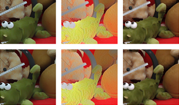
Translucency results. From left to right: Original image; translucency with parameters S(HAA, 7), R(HAP, −9), and C(LAA, 10) using intrinsic layers (reflectance, shading, and specularity) calculated by our own method; and translucency with parameters S(HAA, −15), R(HAP, −10), and C(LAA, 7). While our intrinsic layers are not perfect, we nevertheless achieve a convincing translucent look. Original image and ground-truth intrinsic images are taken from [69].
Intrinsic Specularity Layer: Humans make use of shine and gloss information to classify objects into different categories. By making an object look more shiny, one can make the material appear more plastic or metal like. By boosting all coefficients in the specularity layer we can increase the overall specularity of the objects, thereby making it look less diffuse and more metallic (Fig. 4(d)).
Multiple Intrinsic Layers: By sifting the combination of intrinsic layers we can achieve other interesting appearance edits such as wet paint (Fig. 4(f)), wet-oily/metallic look (Fig. 5(a)), and weathering (Fig. 5). The weathering effect can be further enhanced by desaturating the chroma channels of reflectance layer (see Figure 7 second row).
5.3
Comparison with Boyadzhiev et al.
Please note that some effects mentioned till now can also be partly achieved by simply sifting the luminance channel of an image [12]. However, in the latter case only moderate boost or reduce factors are typically applicable due to possible unnatural look or even explicit artifacts (Fig. 5). The obvious reason for such artifacts is poorer selectivity of edited signal in the luminance channel. As shown in Fig. 5(a) and (c), sifting shading and specularity is more robust than sifting the entire luminance with similar factor. Similarly, more convincing weathered look can be achieved by boosting shading, and reducing reflectance and specularity, which is not possible when a single luminance channel is edited (see Fig. 5(d), Figure 8). Moreover, all our sifting examples are performed on pixel intensity channel given by, In=r2+g2+b2, where r, g, and b are the color channels, instead of luminance L = 0.2126r + 0.7152g + 0.0722b. We observed that by using In instead of luminance L, sifting becomes more robust against color artifacts. In the supplementary material, we provide additional results showing how the range of edits is increased in our case as compared to [12].
5.4
New Appearance Effects
By making use of multiple intrinsic layers we produce new appearance effects which were not possible by simple 2D image filtering to the best of our knowledge. Please note that attempts have been made to achieve such appearance editing using only images [5, 62]. However, that involved partial to full inverse rendering.
Translucency: is one of the important effects in this category. As proposed by [7], inverting the high-frequency components of shading layer makes an object appear more translucent. Inspired by their work, we propose techniques which add up to produce a realistic translucent look. By inverting the high-frequency coefficients of both shading and reflectance layers we achieve a certain degree of translucency. We can enhance this effect further by smoothing and desaturating the chroma channels of the reflectance layer. In order to make translucency effect look more realistic we take inspiration from the work of [5], and in-paint the background within the object boundaries (Figures 9 and 10). By refraining from such in-painting and using a more moderate boosting coefficients we can achieve a pearl-like look (Fig. 4(e)). In [63] the authors have discussed how to reconstruct the background, behind occlusions, using synthetic aperture refocusing. The synthetic aperture technique can also be used for moderately sparse light fields. In [64] the authors get rid of reflections and occlusions to separate an image into occlusions/reflections and a clear background. For our transparent appearance edit, where the background is typically distorted due to refraction and blurred, a rough approximation of background is enough. We believe that such ideas for background reconstruction can greatly improve the realism of our transparent edits. We leave detailed investigations in this regard as future work.
Wetness: appearance edit is inspired from a recent work of Shimano et al. [66], where the authors conclude two fundamental characteristics of a wet surface appearance: darkening and spectral sharpening. We perform darkening on reflectance layer by reducing its intensity, spectral sharpening is achieved by increasing the saturation of chroma channels of reflectance layer. We further enhance this effect by amplifying the fine shape details of an object by manipulating the shading layer (Figure 11).
Depth-guided Selective Filtering: In case of light field, we can create depth maps for a given scene using off-the-shelf depth estimation techniques. We can then make use of these depth maps to selectively target objects at different depths for all the effects mentioned previously e.g., by modulation of editing magnitude (effectively, the coefficient κ in Eq. 11) as a function of depth as demonstrated in Figure 12. Please note that the appearance editing is more pronounced for the objects in front.
6.
Evaluation Results
In this section, we present an evaluation of the two key components of our framework: intrinsic image decomposition and extended band sifting. To this goal we use five real-world datasets [60, 6770]. Ground-truth intrinsic data is only available for the stereo in [69]. Due to space limit, some of our results are presented in the supplementary materials and videos. We also discuss the computational complexity for all key components of our technique. Finally, we present user interaction scenarios for material appearance editing.
Figure 10.
Translucency effect produced using our intrinsic decomposition and sifting-based editing. Original image is taken from [65].
Figure 11.
Wetness effect applied to the chair (from Fig. 8 top left). Original image is taken from [67].
Figure 12.
Cropped Couch scene from the Disney dataset and its wrinkled version that is increasingly blended with the original image as a function of depth.
6.1
Light-field Intrinsic Image Decomposition
Since intrinsic image decomposition is a well-established research problem on its own, in this section we evaluate our decomposition approach as presented in Section 4 with respect to the state-of-the-art methods for single images [20], RGB-D [15], video [17], stereo-image pairs [16, 51], and light fields [2, 3].
Note that we do not compare against multi-view methods like [71, 72] since they use a 360 coverage of the object, which require that either the environment map or the true geometry is given, and each of their scenes contains a single object. We further exclude works like [73] since they require a single known light source, single object, and user interaction.
Figs. 2 and 3 compare our results with respect to [2, 1517, 20], where typically we produce more consistent and shading-free reflectance for sparsely sampled light-field data. For example in Fig. 3, other methods label reflectance edges as shading specially on the eyes and numbers. Note that our results are not only consistent among views, but also within each view and do not exhibit patch-like artifacts. Recently, Bonneel et al. [58] showed promising results on improving consistency across views for the reflectance layer as produced by existing methods. Yet, achieving consistency within an image had remained a challenging task, which we address using our optimization scheme. We further show in the supplementary material and video results that our light-field decomposition is more consistent than simply applying Bonneel et al. consistency scheme to the per-view intrinsic image decomposition. Figure 13 shows that unlike [51], in our results the missing correspondence between views due to occlusions does not result in artifacts, and we recover consistent reflectance.
Figure 14 compares our method with [3]. Both [2] and [3] leverage the dense light-field structure and rely on its small baseline, and hence would not handle sparse light fields (10–20 cm baselines). Nevertheless, we compare our performance with these methods by applying our intrinsic image decomposition on a sparse subsample of dense light-field data.
6.2
Appearance Editing Using Intrinsic Layers
Here we evaluate the performance of our appearance editing framework using intrinsic image layers estimated by our method. Fig. 9 presents our Translucency operation on stereo images of [69] (15 cm baseline). We compare the results when using intrinsic layers estimated by our method versus the ground truth. While our method has misclassified some of the reflectance edges as shading edges, the perceptual quality of the final result has not particularly suffered. Furthermore, Fig. 7 presents results of applying our full framework using intrinsic layers estimated by our method on three different scenes.
Figure 13.
Comparison of the reflectance layer extraction using ours (bottom row) and Maurer et al. [51] (top row) methods on a multi-view stereo dataset. Note that due to occlusion the method by Maurer et al. produces artifacts to the right of the fountain. Our results with and without white balancing show that in some cases (especially outdoors) white balancing the image is not necessary. In our optimization scheme the pre-processing step for white balancing can be enabled/disabled by setting a flag. Original image is taken from (fountain-P11 scene) [68].
Figure 14.
Comparison of our intrinsic image decomposition with the work of Alperovich and Goldluecke [3]. Original image is taken from [70].
6.3
Performance
In this section, we discuss the performance of our complete pipeline for an example 1D (only horizontal parallax) light field composed of 101 × 1 views of spatial resolution 960 × 720 (Fig. 2 Reading Room).
6.3.1
Light-Field Intrinsic Decomposition:
As the first pre-processing step we extract the specular layer for each view. It takes 14–15 s per view for specularity extraction. In the next step we subsample the light field and extract 11 sparse views for intrinsic decomposition. The intrinsic decomposition, including white balancing, of 11 views takes 70–80 min on average. The sparse results are then propagated across remaining 90 views to get dense results. The propagation step takes 30–35 s per view on average. Please note that both for intrinsic decomposition and consistent propagation step we assume that we already have the optical flow values for computing correspondence between views. Thus our unoptimized matlab code for intrinsic decomposition and consistent propagation, as a whole, takes approximately 1.5 min per view. The unoptimized matlab code runs on a Windows 64 bit machine with 32 GB RAM and Intel Xeon CPU (3.50 GHz, 2 processors).
6.3.2
Interactive Appearance Editing:
Once we have the intrinsic layers of reflectance, shading and specularity for each view we can proceed with appearance editing. Our interactive image editing interface, takes as an input a selected view of the light field and its corresponding intrinsic layers. The GPU implementation of the subband creation takes 1–1.5 s, which is a one time process. The GPU implementation of intrinsic layers sifting, then allows a user to interactively manipulate the image appearance at the rate of 50–60 ms per edit. We then apply similar edits on all the views of the light field, which takes 1–1.7 s per view. The above parallel C + + implementation is based on OpenCV and CUDA (using Nvidia GTX 970 GPU).
6.4
User Interaction
The interactive interface allows a user to play with different parameters for a single image. Please note that many of the high-level appearance edits (such as “old” look shown in Fig. 8) involve combinations of parameters that remain in certain relation while performing manipulations. To simplify the editing task we provide a single slider to perform such aggregated parameter changes as demonstrated in the supplemental video. The intuitive interface enables us to quickly find the parameter values for the desired appearance which can later be applied to all the views. Due to our consistent intrinsic layer decomposition, regularity is maintained between views for different appearance modifications.
We could further simplify the user navigation over the parameter choices by developing a collaborative editing system [74] that registers parameter configurations that are often selected by the users. Alternatively, crowd sourcing can be used to learn such meaningful parameter configurations [75]. We could then enable sampling from such parameter distributions to obtain meaningful appearance variations, possibly supported by image-gallery-style user interfaces [76]. We relegate such interaction scenarios as future work.
7.
Discussion
Our goal is to handle various possibilities by providing a generic framework which works for different sources of data and different types of objects and materials. All the mentioned appearance editing operations are applicable for single image and video as well. We do not require the user to switch to light field, however in case of light fields we assure better quality through per-view consistency. Moreover in case of light fields, depth computation is straightforward which is necessary for depth-guided appearance editing.
One aspect which we have not considered in our material editing framework is that of applying multiple sifting operations on the same intrinsic layer. For example, S(HLA, 4) and S(LHN, −3). Such operations can be applied in a cascading manner one after another or in a parallel fashion. If done in parallel, we can use different ways to combine these outputs, for example by taking a linear combination.
7.1
Limitations
While our translucent appearance effect performs well on the object itself and produces the desired result, cast shadows and reflections of the object on its surrounding also need to be accordingly corrected. Figure 15 demonstrates a failure case example where the object has taken a translucent appearance that no longer matches its reflection.
Figure 15.
Translucency effect produced using our full framework. Please note that the shadow of the object does not look proper along with it is translucent counterpart. Original image is taken from [65].
Finally, we believe improving specular layer extraction and using a multi-illuminant illumination estimation method to be good avenues for future work.
8.
Conclusion
We present a framework for intrinsic image-based surface appearance editing on wide-baseline light-field data. We extract reflectance and shading layers by jointly optimizing on different views to maintain both angular and spatial consistency improving over the state-of-the-art solutions. We present a rich variety of perceptual appearance editing effects by filtering each intrinsic layer separately in terms of frequency, amplitude, and sign. We demonstrate that our intrinsic image-based filtering improves over previous luminance-based solutions in terms of robustness, as well as enables new appearance effects like wetness, translucency, pearlescence. Unlike full inverse rendering, we do not require geometry or environment map information. Our modular framework facilitates future extensions. The project web page with supplementary material and more results is available at http://light-field-appearance-intrinsic.mpi-inf.mpg.de/.
Acknowledgments
The authors would like to thank Osman Ali Mian and Zeeshan Khan Suri for their help during this project. They would also like to thank Abhimitra Meka and Elena Garces for kindly providing the necessary comparisons. They thank the reviewers for their insightful comments. The project was supported by the Fraunhofer and Max Planck cooperation program within the German pact for research and innovation (PFI).
References
1FoesselS.ZillyF.SchöberlM.SchäferP.ZieglerM.KeinertJ.Light-field acquisition and processing system for film productionsSMPTE 2013 Annual Technical Conf. Exhibition2013SMPTEWhite Plains, NY181–8
2GarcesE.EchevarriaJ. I.ZhangW.WuH.ZhouK.GutierrezD.2017Intrinsic light field imagesComput. Graph. Forum3610.1111/cgf.13154
3AlperovichA.GoldlueckeB.LaiS.-H.LepetitV.NishinoK.SatoY.A variational model for intrinsic light field decompositionComputer Vision – ACCV 20162017Springer International PublishingCham668266–82
4BergmannS.RitschelT.DachsbacherC.Interactive appearance editing in rgb-d imagesProceedings Vision, Modeling & Visualization2006ACMNew York, NY
5KhanE. A.ReinhardE.FlemingR. W.BülthoffH. H.2006Image-based material editingACM Trans. Graph.25654663654–6310.1145/1141911.1141937
6DuchêneS.RiantC.ChaurasiaG.Lopez-MorenoJ.LaffontP.-Y.PopovS.BousseauA.DrettakisG.2015Multi-view intrinsic images of outdoors scenes with an application to relightingACM Trans. Graph.34164:1164:16164:1–164:1610.1145/2756549
7FlemingR. W.BülthoffH. H.2005Low-level image cues in the perception of translucent materialsACM Trans. Appl. Perception2346382346–8210.1145/1077399.1077409
8FlemingR.2012Human perception: Visual heuristics in the perception of glossinessCurr. Biol.22865866865–610.1016/j.cub.2012.08.030
9MotoyoshiI.NishidaS.SharanL.AdelsonE. H.2007Image statistics and the perception of surface qualitiesNature447206209206–910.1038/nature05724
10SharanL.LiY.MotoyoshiI.NishidaS.AdelsonE. H.2008Image statistics for surface reflectance perceptionJ. Opt. Soc. Am. A25846865846–6510.1364/JOSAA.25.000846
11GieselM.ZaidiQ.2013Frequency-based heuristics for material perceptionJ. Vis.13710.1167/13.14.7
12BoyadzhievI.BalaK.ParisS.AdelsonE.2015Band-sifting decomposition for image-based material editingACM Trans. Graph.3410.1145/2809796
13BarrowH.TenenbaumJ.HansonA.RisemanE.Recovering intrinsic scene characteristics from imagesComputer Vision Systems1978Academic PressNew York3263–26
14BonneelN.KovacsB.ParisS.BalaK.2017Intrinsic decompositions for image editingComput. Graphics Forum36593609593–60910.1111/cgf.13149
15ChenQ.KoltunV.A simple model for intrinsic image decomposition with depth cuesProc. IEEE Int’l. Conf. on Computer Vision (ICCV)2013IEEEPiscataway, NJ241248241–8
16XieD.LiuS.LinK.ZhuS.ZengB.Intrinsic decomposition for stereoscopic imagesIEEE Int’l Conf. on Image Processing (ICIP)2016IEEEPiscataway, NJ174417481744–8
17MekaA.ZollhöferM.RichardtC.TheobaltC.2016Live intrinsic videoACM Trans. Graph.35109:1109:14109:1–109:1410.1145/2897824.2925907
18LaffontP.-Y.BousseauA.DrettakisG.2013Rich intrinsic image decomposition of outdoor scenes from multiple viewsIEEE Trans. Vis. Comput. Graphics19210224210–2410.1109/TVCG.2012.112
19ArtusiA.BanterleF.ChetverikovD.2011A survey of specularity removal methodsComput. Graphics Forum30220822302208–3010.1111/j.1467-8659.2011.01971.x
20BellS.BalaK.SnavelyN.2014Intrinsic images in the wildACM Trans. Graph.33159:1159:12159:1–159:1210.1145/2601097.2601206
21TaoM. W.SuJ.-C.WangT.-C.MalikJ.RamamoorthiR.2016Depth estimation and specular removal for glossy surfaces using point and line consistency with light-field camerasIEEE Trans. Pattern Anal. Mach. Intell.38115511691155–6910.1109/TPAMI.2015.2477811
22SulcA.AlperovichA.MarniokN.GoldlueckeB.Reflection separation in light fields based on sparse coding and specular flowProc. Conf. on Vision, Modeling & Visualization2016Eurographics AssociationGoslar Germany137144137–44
23GryaditskayaY.MasiaB.DidykP.MyszkowskiK.SeidelH.-P.Gloss editing in light fieldsProc. Conf. on Vision, Modeling & Visualization (VMV)2016Eurographics AssociationGoslar Germany127135127–35
24ChadwickA.KentridgeR.2015The perception of gloss: a reviewVis. Res.109221235221–3510.1016/j.visres.2014.10.026
25FarbmanZ.FattalR.LischinskiD.SzeliskiR.2008Edge-preserving decompositions for multi-scale tone and detail manipulationACM Trans. Graph.2767:167:1067:1–67:1010.1145/1360612.1360666
26FattalR.AgrawalaM.RusinkiewiczS.“Multiscale shape and detail enhancement from multi-light image collections,” ACM Trans. Graph. 26 (2007)
27ParisS.HasinoffS. W.KautzJ.2011Local laplacian filters: Edge-aware image processing with a laplacian pyramidACM Trans. Graph.3068:168:1268:1–68:1210.1145/2010324.1964963
28GastalE.OliveiraM.2011Domain transform for edge-aware image and video processingACM Trans. Graph.3069:169:1269:1–69:1210.1145/2010324.1964964
29BaeS.ParisS.DurandF.2006Two-scale tone management for photographic lookACM Trans. Graph.25637645637–4510.1145/1141911.1141935
30ChenQ.XuJ.KoltunV.Fast image processing with fully-convolutional networksIEEE International Conf. on Computer Vision, (ICCV)2017IEEE Computer SocietyVenice, Italy251625252516–25
31WuG.MasiaB.JaraboA.ZhangY.WangL.DaiQ.ChaiT.LiuY.2017Light field image processing: An overviewIEEE J. Sel. Top. Signal Process.11926954926–5410.1109/JSTSP.2017.2747126
32BirklbauerC.BimberO.2012Light-field retargetingComput. Graphics Forum31295303295–30310.1111/j.1467-8659.2012.03008.x
33ChenB.OfekE.ShumH.-Y.LevoyM.Interactive deformation of light fieldsProc. 2005 Symposium on Interactive 3D Graphics and GamesI3D ’052005ACMNew York, NY139146139–46
34FrigoO.GuillemotC.Epipolar plane diffusion: An efficient approach for light field editingProc. of British Machine Vision Conf. (BMVC)2017British Machine Vision AssociationDurham, UK
35HornD. R.ChenB.Lightshop: Interactive light field manipulation and renderingProc. 2007 ACM Symposium on Interactive 3D Graphics and GamesI3D ’072007ACMNew York, NY121128121–8
36ZhangZ.WangL.GuoB.ShumH.-Y.2002Feature-based light field morphingACM Trans. Graph.21457464457–6410.1145/566654.566602
37SeitzS.KutulakosK.2002Plenoptic image editingInt. J. Comput. Vis.48115129115–2910.1023/A:1016046923611
38JaraboA.MasiaB.BousseauA.PellaciniF.GutierrezD.“How do people edit light fields?,” ACM Trans. Graph. 33, 146:1–146:10 (2014)
39WilliemW.ShonK. W.ParkI. K.2016Spatio-angular consistent editing framework for 4d light field imagesMultimedia Tools Appl.75166151663116615–3110.1007/s11042-016-3754-y
40JaraboA.MasiaB.GutierrezD.Efficient propagation of light field editsProc. of the V Ibero-American Symposium in Computer GraphicsSIACG 20112011Faro, Portugal758075–80
41SunH.LiP.ShengB.Image-based material restyling with fast non-local means filteringInternational Conference on Image and Graphics2009841846841–6
42VergneR.BarlaP.FlemingR. W.GranierX.2012Surface flows for image-based shading designACM Trans. Graph.3194:194:994:1–910.1145/2185520.2185590
43XueyS.WangJ.TongX.DaiQ.GuoB.2008Image-based material weatheringComput. Graph. Forum27617626617–2610.1111/j.1467-8659.2008.01159.x
44YeungS.-K.TangC.-K.BrownM. S.KangS. B.2011Matting and compositing of transparent and refractive objectsACM Trans. Graph.302:12:132:1–2:1310.1145/1899404.1899406
45Di RenzoF.CalabreseC.PellaciniF.2014Appim: Linear spaces for image-based appearance editingACM Trans. Graph.33194:1194:9194:1–910.1145/2661229.2661282
46DrorR. O.AdelsonE. H.WillskyA. S.Recognition of surface reflectance properties from a single image under unknown real-world illuminationProc. IEEE Workshop on Identifying Objects Across Variations in Lighting2001IEEEPiscataway, NJ181–8
47OstrovskyY.CavanaghP.SinhaP.2005Perceiving illumination inconsistencies in scenesPerception3410.1068/p5418
48YeG.GarcesE.LiuY.DaiQ.GutierrezD.“Intrinsic video and applications,” ACM Trans. Graph. 33, 80:1–80:11 (2014)
49GrosseR.JohnsonM.AdelsonE.FreemanW.Ground truth dataset and baseline evaluations for intrinsic image algorithmsIEEE ICCV2009IEEEPiscataway, NJ233523422335–42
50Van De WeijerJ.GeversT.GijsenijA.Edge-based color constancyIEEE Transactions on Image Processing2007Vol. 16IEEEPiscataway, NJ220722142207–14
51MaurerD.JuY.-C.BreußM.BruhnA.WilsonR. C.HancockE. R.SmithW. A. P.Combining shape from shading and stereo: a variational approach for the joint estimation of depth, illumination and albedoProc. British Machine Vision Conference (BMVC)2016BMVA PressDurham, UK76.176.1476.1–76.14
52ZhaoQ.TanP.DaiQ.ShenL.WuE.LinS.A closed-form solution to retinex with nonlocal texture constraintsIEEE Transactions on Pattern Analysis and Machine Intelligence (PAMI)2012Vol. 34IEEEPiscataway, NJ143714441437–44
53Van De WeijerJ.GeversT.SmeuldersA. W.Robust photometric invariant features from the color tensorIEEE Trans. on Image Proc.2006Vol. 15IEEEPiscataway, NJ118127118–27
54SunD.RothS.LewisJ. P.BlackM. J.Learning Optical Flow2008SpringerBerlin, Heidelberg
55BlackM. J.AnandanP.1996The robust estimation of multiple motionsComput. Vis. Image Underst.637510475–10410.1006/cviu.1996.0006
56KimS.-J.KohK.LustigM.BoydS.GorinevskyD.2007An interior-point method for large-scale l1 regularized least squaresIEEE J. Sel. Top. Signal Process1606617606–1710.1109/JSTSP.2007.910971
57GehlerP. V.RotherC.KiefelM.ZhangL.SchölkopfB.Recovering intrinsic images with a global sparsity prior on reflectanceProc. 24th Int’l. Conf. on Neural Information Processing SystemsNIPS’112011Curran Associates Inc.USA765773765–73
58BonneelN.TompkinJ.SunkavalliK.SunD.ParisS.PfisterH.2015Blind video temporal consistencyACM Trans. Graph.34196:1196:9196:1–910.1145/2816795.2818107
59BonneelN.TompkinJ.SunD.WangO.SunkavalliK.ParisS.PfisterH.2017Consistent video filtering for camera arraysComput. Graphics Forum36397407397–40710.1111/cgf.13135
60KimC.ZimmerH.PritchY.Sorkine-HornungA.GrossM.“Scene reconstruction from high spatio-angular resolution light fields,” ACM Trans. Graph. 32, 73:1–73:12 (2013)
61BeigpourS.KolbA.KunzS.A comprehensive multi-illuminant dataset for benchmarking of intrinsic image algorithmsProceedings IEEE Int’l. Conf. on Computer Vision (ICCV)2015IEEEPiscataway, NJ172180172–80
62GutierrezD.SeronF. J.Lopez-MorenoJ.SanchezM. P.FandosJ.ReinhardE.2008Depicting procedural caustics in single imagesACM Trans. Graph.27120:1120:9120:1–910.1145/1409060.1409073
63VaishV.LevoyM.SzeliskiR.ZitnickC. L.KangS. B.Reconstructing occluded surfaces using synthetic apertures: Stereo, focus and robust measuresIEEE Conf. on Computer Vision and Pattern Recognition (CVPR)CVPR ’062006233123382331–8
64XueT.RubinsteinM.LiuC.FreemanW. T.2015A computational approach for obstruction-free photographyACM Trans. Graph.3479:179:1179:1–79:1110.1145/2766940
65LiangC.-K.ChungC.2006Image-based material editing. Available http://chiakailiang.org/project_ibme/
66ShimanoM.OkawaH.AsanoY.BiseR.NishinoK.SatoI.Wetness and color from a single multispectral imageIEEE Conf. on Computer Vision and Pattern Recognition (CVPR)2017IEEEPiscataway, NJ321329321–9
67AdhikarlaV. K.VinklerM.SuminD.MantiukR. K.MyszkowskiK.SeidelH.DidykP.Towards a quality metric for dense light fields2017 IEEE Conference on Computer Vision and Pattern Recognition (CVPR)2017IEEEPiscatway, NJ372037293720–9
68StrechaC.Von HansenW.Van GoolL.FuaP.ThoennessenU.On benchmarking camera calibration and multi-view stereo for high resolution imageryIEEE Conf. on Computer Vision and Pattern Recognition (CVPR)2008IEEEPiscataway, NJ181–8
69BeigpourS.HaM. L.KunzS.KolbA.BlanzV.Multi-view multi-illuminant intrinsic datasetProc. British Machine Vision Conference (BMVC)2016British Machine Vision AssociationDurham, UK10.110.1310.1–10.13
70WannerS.MeisterS.GoldlückeB.Datasets and benchmarks for densely sampled 4d light fieldsProc. Vision, Modeling & Visualization2013Eurographics Association225226225–6
71OxholmG.NishinoK.Shape and reflectance estimation in the wildIEEE Transactions on Pattern Analysis and Machine Intelligence (PAMI)2016Vol. 38IEEEPiscataway, NJ376389376–89
72LombardiS.NishinoK.Reflectance and illumination recovery in the wildIEEE Transactions on Pattern Analysis and Machine Intelligence (PAMI)2016Vol. 38IEEEPiscataway, NJ129141129–41
73WangT.-C.ChandrakerM.EfrosA. A.RamamoorthiR.Svbrdf-invariant shape and reflectance estimation from light-field camerasIEEE Conf. on Computer Vision and Pattern Recognition (CVPR)2016IEEEPiscatway, NJ545154595451–9
74TaltonJ. O.GibsonD.YangL.HanrahanP.KoltunV.2009Exploratory modeling with collaborative design spacesACM Trans. Graph.28167:1167:10167:1–167:1010.1145/1618452.1618513
75KoyamaY.SakamotoD.IgarashiT.Crowd-powered parameter analysis for visual design explorationProc. 27th Annual ACM Symposium on User Interface Software and TechnologyUIST ’142014ACMNew York657465–74
76MarksJ.AndalmanB.BeardsleyP. A.FreemanW.GibsonS.HodginsJ.KangT.MirtichB.PfisterH.RumlW.RyallK.SeimsJ.ShieberS.Design galleries: A general approach to setting parameters for computer graphics and animationProc. 24th Annual Conf. on Computer Graphics and Interactive TechniquesSIGGRAPH ’97ACMNew York, NY389400389–400