Back to articles
JIST-first
Volume: 35 | Article ID: ISS-333
Image
Wide-viewing-zone Light-field Capturing Using Turtleback Convex Reflector
  DOI :  10.2352/J.ImagingSci.Technol.2022.66.6.060406  Published OnlineNovember 2022
Abstract
Abstract

Light field cameras have been used for 3-dimensional geometrical measurement or refocusing of captured photo. In this paper, we propose the light field acquiring method using a spherical mirror array. By employing a mirror array and two cameras, a virtual camera array that captures an object from around it can be generated. Since large number of virtual cameras can be constructed from two real cameras, an affordable high-density camera array can be achieved using this method. Furthermore, the spherical mirrors enable the capturing of large objects as compared to the previous methods. We conducted simulations to capture the light field, and synthesized arbitrary viewpoint images of the object with observation from 360 degrees around it. The ability of this system to refocus assuming a large aperture is also confirmed. We have also built a prototype which approximates the proposal to conduct a capturing experiment in order to ensure the system’s feasibility.

Subject Areas :
Views 2
Downloads 0
 articleview.views 2
 articleview.downloads 0
  Cite this article 

Hiroaki Yano, Tomohiro Yendo, "Wide-viewing-zone Light-field Capturing Using Turtleback Convex Reflectorin Electronic Imaging,  2022,  pp 060406-1 - 060406-11,  https://doi.org/10.2352/J.ImagingSci.Technol.2022.66.6.060406

 Copy citation
  Copyright statement 
Copyright © Society for Imaging Science and Technology 2022
  Article timeline 
  • received June 2022
  • accepted November 2022
  • PublishedNovember 2022

Preprint submitted to:
jist
JIMTE6
Journal of Imaging Science and Technology
J. Imaging Sci. Technol.
1062-3701
1943-3522
Society for Imaging Science and Technology
1.
Introduction
Visual information is most commonly represented on a 2-dimensional image by an array of pixels, that is intensity distribution function of P(x, y). However, the actual visions differ from the observer’s point of view due to the 3-dimensional shape of objects, the reflections and refractions of light. By taking this into account, it is known that visual information can be described in light field P(x, y, θ, φ), that is, the combination of 2-dimensional positions (x and y) where light ray passes through a reference surface and 2-dimensional directions (θ and φ) of the light propagation [1]. This field of light has a use of refocusing [2], 3-dimensional geometrical measurement [3] or displaying the light field of an actual object [4]. In most cases, the reference surface of the light field is a plane. In contrast, this study uses a hemispherical reference surface encircling an object to capture the light rays radiated from it (Figure 1(a)). The captured light field enables arbitrary viewpoints of image synthesis in a wide range of viewing angles and refocusing that assumes an extra-large aperture.
Figure 1.
(a) The format of target light field. We aim to capture the light field with a hemispherical reference surface that radiates from an object. (b) Light rays reflection on the ellipsoidal surface. The ray that radiates from one focus point will concentrate on another focus point. (c) Capturing system using flat mirror array that approximates the ellipsoidal surface. The system can capture the object with a virtual camera array generated from an actual camera. (d) Our proposal using a convex mirror array can capture larger objects compared to the flat-mirror-array-based method.
A typical method to capture light rays that pass through the hemispherical reference surface is by employing a camera array which surrounds the object. Each camera captures the images that represent ray color differences in respective position of rays. The angular difference of rays appears in the image difference between cameras. Thus, the camera array can capture a 4-dimensional light field P(x, y, θ, φ). However, this method is expensive, and the physical size of cameras makes it difficult to achieve a dense camera array. In other words, the directional resolution of a light field is limited in this method. A mirror-array-based method [5] was proposed to form a high-density virtual camera array. Based on the paper, a camera with a wide field of view captures a multi-view image of the object from the reflection of the mirror array. Capturing light field on a hemispherical virtual camera array requires two pairs of a mirror array and a camera (Fig. 1(c)).
In this flat mirror array, each mirror clips the field of view of the actual camera and generates a virtual camera. The number of the virtual cameras is the same as the number of mirrors, whereas the mirror size and the distance between the mirror to the camera determine the field of view of the virtual camera. In order to increase the number of virtual cameras, the size of each mirrors should be reduced, assuming constant whole array size. Thus, this method has a tradeoff between the number of virtual cameras and the size of capturing area; it is not suitable for a purpose that requires a large number of virtual cameras. Specifically, Mukaigawa et al. [5] have achieved a 50 virtual camera setup with this method. On the other hand, there is a wide-viewing-zone light-field display that has performed 720 viewpoints [6]. More virtual cameras are required for the capturing system considering its use in light-field display. The capturing system of Mukaigawa et al. that uses a 100 × 90 × 75 mm mirror array has captured a square object of 6 mm on each side. With the aim to increase the number of virtual cameras, the capturing area must be smaller, or the size of the system must be larger.
We thus propose a capturing system that uses ellipsoidal arrays of convex mirrors (Fig. 1(d)). The convex mirrors enable the field of view of each virtual camera to be enlarged. Hence, the system can capture a larger object without reducing the number of virtual cameras. The contributions of our system include:
The capability of achieving a large number of viewpoints as compared to the camera array.
The ability of fast capturing because the system does not employ time multiplexing. The system is also competent in the application of reflectance-field measurement.
The compatibility in situations of capturing large objects or requiring a large number of viewpoints as there is no tradeoff between the number of cameras and the size of captured area, which exists in the flat-mirror-array-based method (Fig. 1(c)).
In this paper, we explain the system designing method, which includes the calculation of convex mirror alignment and radius. Next, we describe simulations to study the capture size and its quality and also an experiment to validate the feasibility of this method and the practical problems.
2.
Previous Works
2.1
Light Field Measurement
The field of light can be described with a 7-dimensional distribution function of light intensity P(θ, φ, λ, t, V x, V y, V z) where V x, V y and V z are 3-dimensional viewpoint positions, θ and φ are 2-dimensional angles, λ is wavelength, and t is time [7]. Assuming the function describes a moment and a specific wavelength, light field will be a function of position and direction. In the area of light field cameras and displays, light field is often described in 4-dimensional function P(x, y, θ, φ) where x and y are 2-dimensional light ray positions on a reference plane, and θ and φ are 2-dimensional direction of light propagation [1, 8].
Most cameras capture images that illustrate light rays intensity from each direction, but the light-field camera captures both the position and direction. Commercially available light-field cameras are achieved by the lens-array-based method that generates multiple viewpoints in a single image sensor [2, 3]. This method is often used to capture light field that passes through a small aperture, and it is mainly utilized for depth measurement and refocusing. In contrast, the camera-array-based method is helpful in capturing a light field that radiates from an object [9].
When capturing light field for displaying with a wide-viewing-zone display system, many viewpoints are required. In this case, the camera-array-based method makes the system more expensive and bulky. Active cameras are used in this field for static objects or objects that have cyclic movement [4, 10]. Our proposal does not use active scanning and captures light field that passes through a hemisphere which encircles the object.
2.2
Reflectance Field Measurement
By recording light fields in various positions of a light source, we can simulate how the appearance of an object changed depending on the ambient light. The recorded data is the 6-dimensional function of light intensity depending on 2-dimensional light source position and 4-dimensional light field. The system consists of a camera array and a light source array [11], and a time-multiplexed system using a high-speed light source array and an active camera [12], which were achieved previously.
The complete field of reflectance is an 8-dimensional function that is a set of 4-dimensional input light field and 4-dimensional output light field [13]. The capturing system of the 8-dimensional reflectance field includes a projector array to generate input light field and a camera array to receive output light field. The ellipsoidal array of flat mirrors [5] and the kaleidoscopic approach [14] have been explored previously to capture reflectance fields. Our approach is an extended method of the ellipsoidal mirror array [5].
An ellipsoid has two focus points, and when rays radiate from one focus point and reflect at the surface, they concentrate at another focus point (Fig. 1(b)). Using this characteristic, an ellipsoidal array of flat mirrors and an actual camera placed at one focus of the ellipsoid can form a camera array that captures the object from another focus point. When using two sets of a mirror array, the system creates a hemispherical camera array (Fig. 1(c)). The co-axial set of camera and projector enables generating both a camera array and a projector array simultaneously around the object, enabling reflectance field measurement. Furthermore, without employing time multiplexing, this method is also suitable to capture the light field of a moving object. However, since there is a tradeoff between capture area size and the number of the virtual cameras, the system is not suitable for a large object or applications that require many viewpoints. Therefore, we aim to overcome this tradeoff using our convex-mirror-based method.
2.3
Convex-mirror-based Multiview Camera Systems
When looking into a flat mirror with a camera, there is a reflected scene in the mirror. In other words, the mirror generates a virtual camera. The mirror size and distance to the camera decide the field of view of the virtual camera. When using a convex mirror, a virtual camera with a wider field of view is achieved because a convex mirror can reflect a wider angle of light rays into an actual camera. The light field capturing [15, 16], multi-viewpoint imaging [17], generating volumetric data [18], and measuring distance [19] are studied previously using convex reflectors.
The multiview camera systems based on multiple spherical mirrors have been explored, but they use only a few variations of curve radius in a system [20]. In contrast, we use a variation of convex reflectors for the effective use of image sensor pixels.
3.
Methods
The proposed system consists of convex mirror arrays and cameras (Fig. 1(d)). The convex mirror array approximates the ellipsoidal surface that concentrates rays from the object toward the camera. The reflected image of the object is in each mirror when looking from the camera, hence creating a multiview image. This multiview image is a light field data whose reference surface is half of the hemisphere that enclose the object. To capture a light field whose reference surface is a hemisphere that encircles the object (Fig. 1(a)), two sets of a convex mirror array and a camera are used. The convex mirror array can support larger objects compared to the flat mirror array (Fig. 1(c)) by enlarging each field of view in the multiview image.
In this section, we describe how we designed the mirror array. The convex mirror array is an extended design of the flat mirror array; the flat mirrors are replaced by spherical convex mirrors with adequate radiuses to capture the spherical area. To design the base of the proposed mirror array, which is a flat mirror array, deciding the number of virtual cameras and alignment of the virtual cameras are required.
3.1
Number of Virtual Cameras and Alignment of the Virtual Cameras
The resolution of the light field can be separated into two types, spatial resolution and directional resolution (Figure 2(a)). By increasing the number of virtual cameras, the range of observing direction increases, and hence achieving a higher directional resolution of the light field. However, the number of pixels in each virtual camera decreases because they share one image sensor. Since each virtual camera is facing towards the reference surface and the pixels correspond to the positions on the surface, the spatial resolution of the light field decreases as the number of virtual cameras increases. Thus, there is a tradeoff between the spatial resolution and the directional resolution of the captured light field. The number of the virtual cameras should be determined by taking this tradeoff into account.
Figure 2.
(a) The relationship of light field resolutions. The spatial resolution is associated with the virtual camera’s resolution. The directional resolution is associated with the number of virtual cameras. (b) The generation of a geodesic polyhedron with given edge separation frequency n. Generated mesh is used to align the camera array.
We defined the directional resolution as the number of virtual cameras and the spatial resolution as the average number of pixels assigned to each captured image. The number of the virtual cameras is determined by simulating the resolutions of different designs, and then determining the appropriate number of virtual cameras that achieves the nearest resolution ratio, which best fits the purpose.
It is necessary to arrange virtual cameras at equal intervals on the hemispherical surface to sample rays at equal angular intervals. Mukaigawa et al. used the vertex of the icosahedron-based geodesic polyhedron as the camera alignment pattern [5]. The geodesic polyhedron achieves an equal interval of vertices on a spherical surface. By recursive surface division, the number of vertices on the surface of the sphere increases. Thus, the density of virtual camera with edge separation frequency of only 2n was considered in the previous study. In contrast, we express camera density using edge separation frequency n to adjust the number of the virtual cameras more flexibly. The method of how to generate a geodesic polyhedron with a given edge separation frequency is shown in Fig. 2(b). The initial polyhedron is a regular icosahedron. To minimize the variation of distances of vertices, we recursively separated each face with prime factors of n.
By simulating the shape of the reflector array at various n, n is determined from the ratio of positional and angular resolution, considering the pixel number of the actual camera.
3.2
Mirror Design
The proposed convex mirror array is designed based on the flat mirror array of Mukaigawa et al. [5]. This flat mirror array approximates an ellipsoidal surface so that it creates the spherical virtual camera array as described in the previous section. The flat mirror array is designed in the following steps:
1.
Define the capture area center Pobj, the actual camera position Pcam, and the ellipsoidal surface whose focus points are at those points.
2.
Define the position of virtual cameras at the vertex of geodesic polyhedron whose center is at Pobj and whose radius is equal to the major axis length d of the ellipsoidal surfaces.
3.
Consider the intersection points of the ellipsoid surface and the line connecting to each position of virtual cameras and Pobj, define flat mirror as the tangent plane on the ellipsoid at the intersection point.
4.
By connecting the neighboring mirrors respectively, the flat mirror array is expressed in a polyhedron.
The initial field of view of each virtual camera 2θ0 is calculated from each surface of the flat mirror array. Since the shape of the view of each virtual camera is a convex polygon, we defined the field of view 2θ0 as the top angle of a viewing cone whose axis’s direction is focusing towards the object area center and it has a maximum size that fits in the polygon (Figure 3).
Figure 3.
The virtual camera array is created by the polygonal mirror array. We defined each field angle as a top angle of the viewing cone whose axis is towards the center of the capture area.
Our system is designed to capture an area with a given radius R. The enlarged field of view 2θ1 is calculated as follows so that the virtual camera can capture the area radius of R (Figure 4), where mirror size l is the minimum distance between the viewing area of the cone axis and the mirror edges. The distance from the center of the capture area and the mirror is dl∕tanθ0.
(1)
θ1=tan1Rldltanθ0.
Figure 4.
The calculation of the spherical convex mirror radius that replaces each flat mirror. We calculated the spherical mirror radius r by calculating the optimal field angle θ1.
The radius of each spherical convex mirror that replaces the flat mirror is calculated as the following equation considering the enlarged field of view from 2θ0 to 2θ1.
(2)
r=lsinθ1θ02.
In the case of a flat mirror array, the field of view of the virtual cameras will be small when the number of mirrors is increased. Our system, which uses convex mirrors, can be designed to capture the required size of the area regardless of the mirror number defined by edge separation frequency n.
4.
Simulations
In this section, we describe the simulations carried out to confirm the validity of the proposed method. We first designed the simulation system and then simulated the capture area size by comparing with the previous study. To characterize the captured light field, we synthesized arbitrary viewpoint images and conducted refocusing. We also simulated how the image sensor resolution can improve the image quality of synthesized views.
4.1
Simulation Properties and Capture Area Size Compared to the Previous Study
The simulation property is shown in Table I. The overview of the simulated system is depicted in Figure 5(a). The ellipsoid of mirror array and real camera parameters are determined so that objects in the spherical capture area won’t block the rays projecting from the mirror array toward the real camera. To determine the number of the virtual cameras, we simulated the mirror array in different virtual camera densities n and then plotted the light field resolution (Fig. 5(b)). We adapted the camera density of n = 18, where the positional and angular resolutions are balanced. In other words, the average number of pixels on a virtual camera and the number of virtual cameras are closest to each other at that density.
Figure 5.
(a) Overview of a simulated system. (b) Relationship between the virtual camera density and the light-field resolutions. (c) Relationship between the virtual camera density and the capture area size.
We simulated the capture area size of a flat mirror array in various camera densities as compared to the proposal (Fig. 5(c)). The capture area in this simulation refers to the spherical volume that can be captured by a virtual camera with the smallest field of view. Mukaigawa et al. [5] used a camera array generated from two times recursively separated icosahedron. The density is equal to the geodesic polyhedron pattern whose edge separation frequency is n = 4. The flat mirror array system can capture an area of 21.2 mm diameter with a density of n = 4, whereas an area of only 4.8 mm diameter with a density of n = 18. On the other hand, our system can adjust capture area up to the limit where the object occludes reflectors. In this simulation property, the limit is a diameter of 60 mm. We used convex mirrors to capture a spherical area of 60 mm diameter with the camera density of n = 18 for the simulations and experiments in this manuscript.
Table I.
Simulation specifications.
Capture area diameter60 mm
Real camera resolution2080 × 1552 pixel
Real camera view angle89 (horizontal)
Real camera positionsx = 100 mm, z = −100 mm and x = −100 mm, z = −100 mm from the center of the capture area
Length of the ellipsoid short axis100 mm
Number of virtual camera1657 (Separation number n = 18)
The images captured by the two real cameras are rendered based on ray tracing. The pinhole model is used for the real camera model. The captured object is the Stanford Bunny with a height of 46 mm. The multiview image is captured by a real camera as seen on the rendered image (Figure 6). We then created light-field data from this capture by calculating its ray position and direction pixel-by-pixel.
Figure 6.
Turtle back convex reflector capturing.
4.2
Arbitrary Viewpoint Image Synthesis
Figure 7 is the synthesis result of several viewpoints from the captured light-field data. The synthesis uses the nearest neighbor interpolation of pinhole model rays. We could confirm that convex mirror arrays can capture a larger area than flat mirror arrays can.
Figure 7.
Synthesis results in different viewpoints.
The apparent resolution is lower at higher elevation angles (Fig. 7(b)) because the light rays reflected by the convex mirrors at higher position of the array are captured in fewer pixels in the real camera. Since the mirrors in higher positions are small and far from the real camera, the assigned pixels to the virtual camera which is positioned above the object are fewer than that of the virtual cameras looking at the object from side.
4.3
Refocusing
Figure 8(c) is the synthesised results of an aperture assumed with a diameter of 300 mm and placed 640 mm away from the object center. We confirmed the ability of refocusing by using a large aperture by comparing it with the ground truth (Fig. 8(a)).
Figure 8.
Refocusing results. (a) Ground truth. (b) All focus image of a pinhole model. (c) Result of synthetic aperture from 69 pinhole cameras.
The refocusing is based on the synthetic aperture [21]. Firstly, we synthesized the images captured by pinhole cameras located on the assumed aperture. Then, the focused image is generated by averaging those images. The pinhole camera image (Fig. 8(b)) is generated by the same method as in the previous section. Since nearest-neighbor interpolation is used, there are errors in pixel values of the pinhole images, and by averaging those images, this error causes a blur effect in the focused image.
4.4
Sensor Resolution Versus Synthesized Image Quality
We simulated how apparent image quality changes in different pixel numbers of the image sensor. By increasing the pixels of the image sensor without changing the mirror array design, only the pixel number of each virtual camera will increase. To increase the number of virtual cameras, increasing the number of spherical mirrors is necessary. Thus, changing the mirror array design is required in order to re-balance the positional and directional resolution of the light field when changing the pixel number of the image sensor. In this simulation, the reflector array design is changed for each image sensor (Table II).
Table II.
Balanced resolutions in different image sensor resolutions. n is the icosahedron edge separation frequency used in virtual camera alignment.
Image sensor resolutionNumber of virtual cameraAverage of virtual camera resolution
1040 × 776844 (n = 12)764
2080 × 15521586 (n = 18)1688
4160 × 31043129 (n = 26)3474
8320 × 62086578 (n = 36)6602
The synthesized images are rendered using nearest-neighbor interpolation similar to that in the arbitrary viewpoint image simulation. We compared the image quality using structural similarity (SSIM) [22]. The target is the Stanford Dragon with a height of 40 mm. The result is shown in Figure 9. The result shows that the SSIM index increases linearly to the log of the number of image sensor pixels. For the same pixel number, the apparent resolution is highest at the elevation angle of 15 (similar to that in the arbitrary viewpoint image simulation result seen in Fig. 7(b)). However, the image quality acquired at 15 elevation angle is not the best in the SSIM score because the object’s image size is the largest at that angle.
Figure 9.
Synthesized image comparison in different image sensor resolutions. (a) Synthesized images and ground truth. (b) SSIM evaluation of synthesized images.
5.
Experiments
5.1
Prototyping
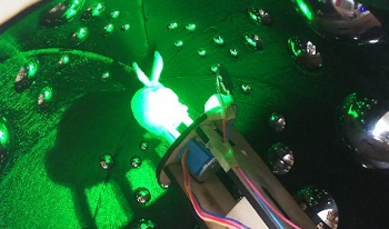
We conducted prototyping and capturing experiments to confirm the feasibility of the proposal. The proposal includes a spherical mirror array which is difficult and expensive for prototyping with the current technology. Thus, we implemented a system that can approximate the proposal using a small number of spherical mirrors on a motorized mirror base (Figure 10).
Figure 10.
Prototype of the capturing system. (a) Simplified structure of capturing system. (b) Close view of capturing stage. 4 LEDs are for locating the convex mirror. (c) 3D model of the mirror base. This holds the steel balls and rotates to change the position of balls. (d) An example of the image captured by the prototype. (e) A multi view image synthesized from the capture of the prototype.
We used a steel ball as a spherical mirror which is affordable but has an accurate sphericity and fine surface. The captured image of the proposal can be synthesized from the images taken when the steel ball with the same radius is at the original spherical mirror position. The spherical mirrors in the proposal are aligned on an ellipsoidal surface. Thus, a single steel ball can approximate multiple convex mirrors in the proposal by attaching steel balls on a base that rotates on the same axis with the ellipsoidal surface.
In this method, the steel ball position is fixed in a non-rotational direction, which is at the elevation angle. Thus, we need to design the position of the steel ball at the elevation angle and also estimate the radius of the steel ball carefully. Smaller radius of the spherical mirror creates a wider viewing angle of the virtual camera and the virtual camera viewing angle tends to be wide when the capture object is close to the mirror. Therefore, there is a correlation between the spherical mirror radius and the elevation angle where the mirror is located. We use k-means clustering to determine the steel ball radiuses and the positions in elevation angle from the correlation.
There are approximations in this design method because multiple mirrors are substituted with a single steel ball that is movable in one direction. Thus, we simulated the reconstructed result before and after the approximation, and there were no significant differences found. Fig. 10(d) shows an example of the captured image. From the images taken at different angles of mirror base, the multiview image is synthesized (Fig. 10(e)).
5.2
Calibration
There are positional errors of mirrors because of the error of machining, assembling, and, positioning of motorized base. We measured mirror position and then created the light-field data according to the measurement.
Before capturing for the light-field acquisition, the four chip LEDs on the base of the object (Fig. 10(b)) are blinked sequentially, and calibration images are obtained. Then the spherical mirror positions are estimated using the LED reflections. This measurement is conducted at every rotation angle repeatedly.
5.3
Capture Result
Figure 11 shows the result of the synthesized view from the light-field data captured by the prototype. We use the finite aperture model, which is similar to the simulations. From Fig. 11(a), we can observe that the viewpoint is changed and from Fig. 11(b), we can see the transition of focus plane. However, the experimental results are more blurry compared to the simulation results. This blur already exists in the captured images (Fig. 10(e)), while there is no blur in simulated images (Fig. 6). The possible cause of this phenomenon is the effect of an optical low-pass filter that is commonly built into the image sensor to reduce aliasing in the camera view.
Figure 11.
Synthesized images from prototype capture. The synthesized aperture diameter is 80 mm and the distance to the capture area center is 160 mm. (a) Viewpoint change. (b) Refocusing.
6.
Limitations and Future Works
Unlike a planer mirror array, the proposal requires a camera with a deeper depth of field. The ellipse has two focal points, and the sum of the distance to its focal point is constant for all points on the curve. In the case of an ellipsoidal surface that has two focal points, light-rays radiating from one focal point concentrate onto another focal point by reflecting it on the surface. Similar to the ellipse, the travel length of the ray is constant. In the planer mirror array method [5], the object is at one focal point of the ellipse, and the camera is at another focal point. Thus, the reflections of the object are located at constant distances from the camera in this method. This enables the employment of a camera with shallow depth of field. On the other hand, our proposal uses convex mirrors instead of planer mirrors. Thus, the reflections of the object are closer to the mirror surface [23]. So, camera with a deeper depth of field is required for our method compared to the previous method. The camera’s aperture must be smaller to gain the depth of field, and hence the captures will get darker. In our experiments, the reflected images of the object exist in the range of 150–250 mm from the camera. The capturing object is lit up brightly and captured with 100 ms of exposure in the experiment.
This manuscript describes the design method to determine camera density from the ratio between the positional resolution and directional resolution. We use a 1:1 ratio in the simulation; however, we should adjust the balance between the resolutions for some purposes. For example, when the diffusive surface is located on the reference surface, the color of the light ray is constant in directions. Likewise, capturing diffusive objects near the reference surface generally requires low directional resolution of the light field. Calculating optimal resolution balance for different purposes can be addressed in the future for practical use.
The radius of each convex mirror is determined so that the images in each mirror are the largest. The size of mirrors near to the capture objects will be smaller in this method. As follows, the pixel numbers assigned to those mirrors will be decreased, and this causes an uneven number of pixels in the virtual cameras. Thus, there will be another optimization method for a consistent resolution of virtual cameras.
7.
Conclusion
We proposed a light-field capturing method that uses a spherical mirror array and two cameras to capture the light field radiating from an object in a wide viewing zone. Since the proposal uses two real cameras to generate a hemispherical virtual camera array, an affordable capturing system with high angular resolution can be achieved. In addition, the spherical mirrors enable the capturing of large objects compared to the previous method which used a flat mirror array.
We conducted simulations to capture light fields and then synthesized arbitrary viewpoint images. Results obtained show that the system could successfully capture the desired size of the object. Also, the ability to refocus assuming an aperture that is larger than the object is verified. The reconstruction quality can be improved by using an image sensor with more pixels. The feasibility of the system is confirmed from the experimental result using a prototype that approximates the proposal. However, the cameras used in the system should have a wider focus range compared to the previous method. Furthermore, since the design of a spherical mirror array has high flexibility, the designing method for different purposes could be developed in the future.
Acknowledgment
This work was supported by JSPS KAKENHI Grant Number 20H04226 and 22K19789. We thank Chloe Choe Wei Ee for proof-reading this manuscript.
References
1GortlerS. J.GrzeszczukR.SzeliskiR.CohenM. F.1996The lumigraphProc. 23rd Annual Conf. on Computer Graphics and Interactive Techniques, SIGGRAPH 1996435443–54ACMNew York, NY10.1145/237170.237200
2NgR.LevoyM.BredifM.DuvalG.HorowitzM.HanrahanP.Light field photography with a hand-held plenoptic camera,” Technical Report (2005)
3AdelsonE. H.WangJ. Y. A.1992Single lens stereo with a plenoptic cameraIEEE Trans. Pattern Anal. Mach. Intell.149910699–10610.1109/34.121783
4JonesA.McDowallI.YamadaH.BolasM.DebevecP.2007Rendering for an interactive 360 light field displayProc. ACM SIGGRAPH Conf. on Computer Graphics1101–10ACMNew York, NY10.1145/1276377.1276427
5MukaigawaY.TagawaS.KimJ.RaskarR.MatsushitaY.YagiY.2011Hemispherical confocal imaging using turtleback reflectorLecture Notes in Computer Science (including subseries Lecture Notes in Artificial Intelligence and Lecture Notes in Bioinformatics)LNCS (PART 1) 6492Vol. 6492336349336–49SpringerBerlin, Heidelberg10.1007/978-3-642-19315-6_26
6YanoH.YendoT.2018Spherical full-parallax light-field display using ball of fly-eye mirrorACM SIGGRAPH 2018 Emerging Technologies, SIGGRAPH ’18ACMNew York, NY10.1145/3214907.3214917
7AdelsonE. H.BergenJ. R.1991The plenoptic function and the elements of early visionComputational Models of Visual Processing3203–20MITCambridge, MA
8LevoyM.HanrahanP.1996Light field renderingProc. 23rd Annual Conf. on Computer Graphics and Interactive Techniques, SIGGRAPH 1996314231–42ACMNew York, NY10.1145/237170.237199
9VaishV.WilburnB.JoshiN.LevoyM.2004Using plane + parallax for calibrating dense camera arraysProc. IEEE Computer Society Conf. on Computer Vision and Pattern RecognitionVol. 1IEEEPiscataway, NJ10.1109/CVPR.2004.1315006
10JonesA.BolasM.McDowallI.DebevecP.2006Concave surround optics for rapid multiview imagingACM SIGGRAPH 2006 Research Posters, SIGGRAPH 2006ACMNew York, NY10.1145/1179622.1179735
11MüllerG.BendelsG.KleinR.2005Rapid synchronous acquisition of geometry and appearance of cultural heritage artefactsVAST’052005132013–2010.2312/VAST/VAST05/013-020
12ChabertC. F.EinarssonP.JonesA.LamondB.MaW. C.SylwanS.HawkinsT.DebevecP.2006Relighting human locomotion with flowed reflectance fieldsACM SIGGRAPH 2006: Sketches, SIGGRAPH ’06ACMNew York, NY10.1145/1179849.1179944
13DebevecP.HawkinsT.TchouC.DuikerH. P.SarokinW.SagarM.2000Acquiring the reflectance field of a human faceProc. ACM SIGGRAPH Conf. on Computer Graphics145156145–56ACMNew York, NY10.1145/344779.344855
14IhrkeI.ReshetouskiI.ManakovA.TevsA.WandM.SeidelH. P.2012A kaleidoscopic approach to surround geometry and reflectance acquisitionIEEE Computer Society Conf. on Computer Vision and Pattern Recognition Workshops293629–36IEEEPiscataway, NJ10.1109/CVPRW.2012.6239347
15TaguchiY.AgrawalA.VeeraraghavanA.RamalingamS.RaskarR.2010Axial-cones: Modeling spherical catadioptric cameras for wide-angle light field renderingACM Trans. Graph.29181–810.1145/1882261.1866194
16UngerJ.WengerA.HawkinsT.GardnerA.DebevecP.2003Capturing and rendering with incident light fieldsEurographics Symp. on Rendering1101–10DTICFort Belvoir, VA
17LanmanD.CrispellD.WachsM.TaubinG.2006Spherical catadioptric arrays: Construction, multi-view geometry, and calibrationProc. – Third Int’l. Symp. on 3D Data Processing, Visualization, and Transmission, 3DPVT 2006818881–8IEEE Computer SocietyPiscataway, NJ10.1109/3DPVT.2006.130
18DingY.YuJ.SturmP.2009Multiperspective stereo matching and volumetric reconstructionProc. IEEE Int’l. Conf. on Computer Vision (ICCV)182718341827–34IEEEPiscataway, NJ10.1109/ICCV.2009.5459406
19KojimaY.SagawaR.EchigoT.YagiY.2005Calibration and performance evaluation of omnidirectional sensor with compound spherical mirrorsWorkshop on Omnidirectional Vision, Camera Networks and Non-classical Cameras (OMNIVIS’05)IEEEPiscataway, NJ(May 2014)
20ReshetouskiI.IhrkeI.2013Mirrors in computer graphics, computer vision and time-of-flight imagingLecture Notes in Computer Science (including subseries Lecture Notes in Artificial Intelligence and Lecture Notes in Bioinformatics)LNCS 82007710477–104SpringerCham
21LevoyM.ChenB.VaishV.HorowitzM.McDowallI.BolasM.2004Synthetic aperture confocal imagingACM SIGGRAPH 2004 Papers, SIGGRAPH 2004825834825–34ACMNew York, NY10.1145/1015706.1015806
22WangZ.BovikA. C.SheikhH. R.SimoncelliE. P.2004Image quality assessment: From error visibility to structural similarityIEEE Trans. Image Process.1310.1109/TIP.2003.819861
23SwaminathanR.2007Focus in catadioptric imaging systemsProc. IEEE Int’l. Conf. on Computer VisionIEEEPiscataway, NJ10.1109/ICCV.2007.4409205